 Often clock jitter induced from the power supply noise, signal routings, or other signals severely degrade the performance of the system. Clock generation and distribution in a FPGA for a high speed analog application is particularly prone to these issues. They manifest themselves in phase noise or clock jitter, which is the random variation of the period of a signal over time. Clearly, optimization of the design requires verification of the integrity of such clocks.
Although there are several methods to measure phase jitter, often a spectrum analyzer is used for the measurement. However, the price of high end spectrum analyzers required for fine measurements is a prohibitive factor for many applications. Other phase measurements techniques are either complicated or simply not accurate. This paper intends to describe a simple, accurate and cost effective technique to measure this parameter.
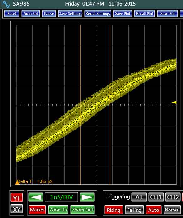
 Fig. 1: Jitter on a clock as shown on an oscilloscopeFor a large amount of jitter, oscilloscopes could be used to measure the parameter. Figure 1 shows an example of this measurement. The accuracy of the measurement depends on the sampling rate of the oscilloscope and also the signal triggering. For example, a 1 GHz sampling rate limits the measurements to about 3 ns peak to peak or .5 ns RMS, assuming a Gaussian noise distribution. Triggering uncertainties of the oscilloscope could double this number to about 6 ns. This presumes the clock jitter of the oscilloscope’s analog to digital converter is negligible. Clearly, for sub nano seconds jitter measurements, the performance of the oscilloscope must be significantly better, which makes it expensive as it is the case for the spectrum analyzer.
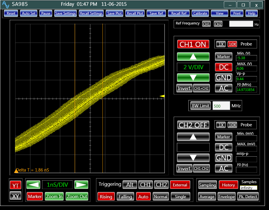
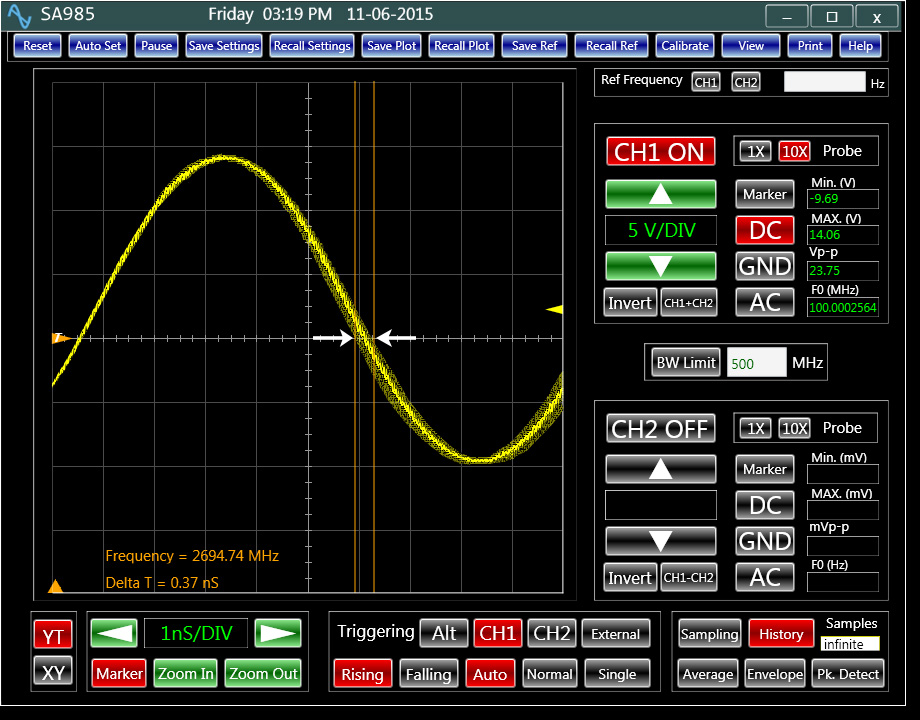
 Fig. 2: Measuring phase jitter based on triggering mechanismFor periodical signals when the measurement of phase noise is applicable, an oscilloscope with more than 50 GHz effective sampling rate offers an ideal alternative to expensive solutions. Analog Arts’ SA987, used in this article, is one such oscilloscope. It uses a low noise synchronization mechanism when triggered on the signal itself. These features make the accuracy and the resolution of the measurement much finer. Triggering on one edge of the signal, the phase noise is the time width of the opposite edge traces over time as shown in figure 2. In this case, the digitizer sampling jitter, the resolution of the oscilloscope time base, and the triggering noise are the main limiting factors. For this set up, a measurement resolution of about 100 pico seconds is achievable.
Performing a finer measurement requires a change in the set up and a simple mathematical operation. The technique relies on the phase measurement between the signal under test and a clean reference signal. Using the other channel of the oscilloscope to capture the master clock of the FPGA provides this reference signal. By correlating the captured signals, their phase difference can be calculated with a fine degree of precision. Correlation is a simple mathematical operation. The theory and applications of the operation is explained thoroughly in many articles [1].
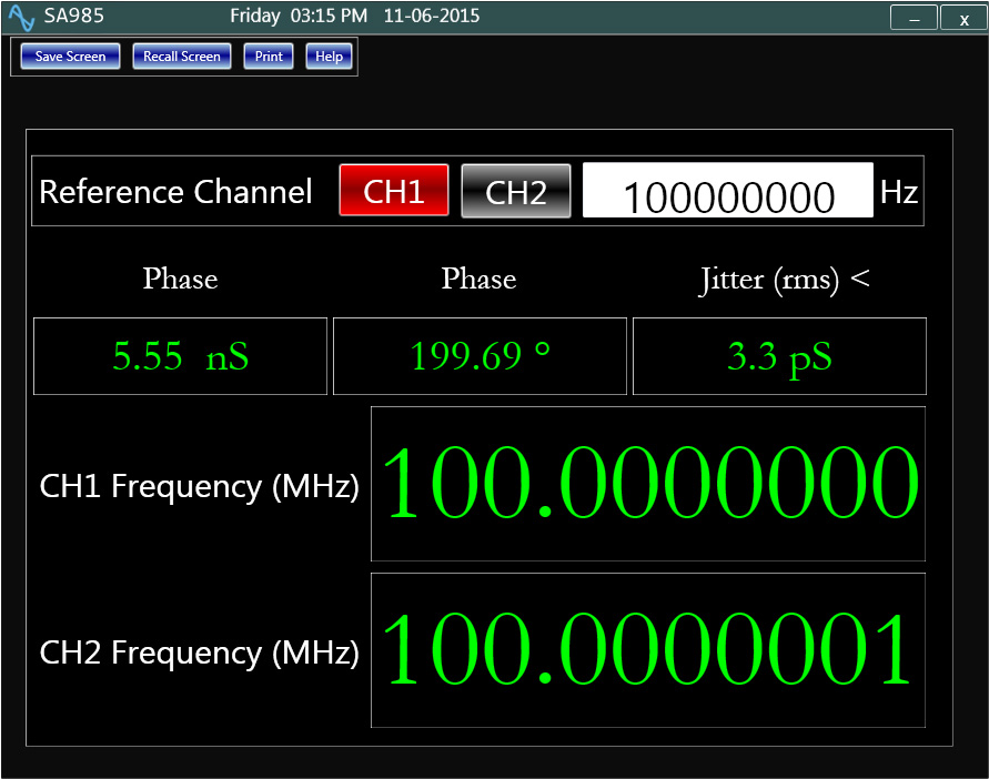
 Fig. 3: Precise phase analyzer developed based on correlation techniqueThe Analog Arts C# program [2] is one implantation of correlation. Every time the signals on the channels are captured, the program calculates the phase between the channels. The variation of this phase constitutes the noise on the clock under test. One important feature of this technique is that it eliminates the need to trigger, a key limiting factor in the previous method. In addition, since both channels of the oscilloscope use the same digitizing clock, sampling related errors are filtered out. Figure 3 illustrates a complete device developed based on this principle. The Measurement process is fully automated and accurate. For a 100 GHz sampling rate, phase noise measurements of about 10 pico seconds can be expected.
There are other techniques, which could enhance the performance of the measurement to sub-picoseconds. That is the subject of the next article in the series.
Author: Hamid Danesh (Project Engineer; Analog Arts Inc.)
References
[1] Wikipedia "CorrelationFunction" - https://en.wikipedia.org/wiki/Correlation_function
[2] Code of C# Program with Correlation Function
int horizontal_resolution;
int[] ch1_signal;
int[] ch2_signal;
double signal_period;
double sampling_res;// sampling resolution
double normalized_period = signal_period / sampling_res;// normalized period
int number_of_period = (int)(horizontal_resolution / normalized_period); // number of periods
// Compute how many data points to use to capture as close as possible
// to an integer number of periods
int span = (int)Math.Round(number_of_period * normalized_period);
if (span >= horizontal_resolution || span <= 0)
span = horizontal_resolution;
// Compute the mean of each signal
double signal1_avg = 0;
double signal2_avg = 0;
for (int i = 0; i < span; i++)
{
signal1_avg += ch1_signal[i];
signal2_avg += ch2_signal[i];
}
signal1_avg /= span;
signal2_avg /= span;
// Compute maximum correlation
int best_offset = 0;
double best_corr = 0;
for (int di = 0; di < span; di++)
{
double corr = 0;
int count = 0;
for (int i = 0; i < span; i++)
{
int j = i + di;
if (j >= horizontal_resolution)
break;
double ch1 = ch1_signal[i] - signal1_avg;
double ch2 = ch1_signal[j] - signal2_avg;
corr += ch1 * ch2;
count++;
}
corr /= count;
if (corr > best_corr)
{
best_corr = corr;
best_offset = di;
}
}

 How to resolve AdBlock issue?