Did you know? |
Can a digitizer be used as an oscilloscope? Read more...
Latest Oscilloscope News |
Test Probes for Signals up to 18 Gb/s
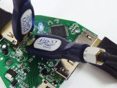 31 October 2016 - Pico Technology launched a new family of high-performance microwave and gigabit test probes. The PicoConnect passive probes allow cost-effective fingertip browsing of broadband signals or data streams out to 9 GHz or 18 Gb/s. These include the now ubiquitous USB 2 & 3, HDMI 1 & 2, Ethernet, PCIe, SATA and LVDS standards.
High-Speed, High-Resolution, High-Voltage PXIe Oscilloscope
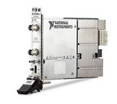 26 October 2016 – National Instruments (NI) announced the PXIe-5164 oscilloscope featuring 100 Vpp maximum input range at 1 GS/s and 14 bits resolution. The PXIe-5164 is built on the open, modular PXI architecture, and includes a user-programmable FPGA to help aerospace/defense, semiconductor and research/physics applications that require high-voltage measurements and high levels of amplitude accuracy.
CAN FD Support for Tektronix Mixed Domain Oscilloscopes
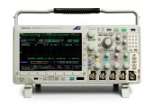 20 October 2016 - Tektronix introduced a complete CAN FD protocol trigger, decode and search solution for its MDO3000 and MDO4000C Series of mixed domain oscilloscopes. The solution helps automotive engineers to meet consumer demand for more capable and sophisticated electronic modules and integrated systems. Automobile manufacturers are increasingly adopting the CAN FD (Controller Area Network with Flexible Data Rate) protocol which allows them to transmit more data inside vehicles.
First Oscilloscope with PSI5 Bus Analysis Support
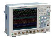 13 October 2016 - Yokogawa announces support for Peripheral Sensor Interface 5 (PSI5) bus analysis on its 8 channel DLM4000 and 2 and 4 channel DLM2000 oscilloscopes. Yokogawa’s PSI5 support is a first for the industry, and makes its oscilloscopes uniquely useful for automotive designers and engineers.
Analyzing CXPI Interfaces for Automotive Applications
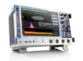 28 September 2016 - The new R&S RTx-K76 CXPI serial triggering and decoding option from Rohde & Schwarz allows users to analyze the clock extension peripheral interface (CXPI) communications bus with R&S RTE and R&S RTO oscilloscopes. Users can decode all protocol details and isolate anomalies by triggering on the corresponding details. This significantly accelerates design verification and implementation of CXPI interfaces.
Analysis of Non-Coherent and Coherent Optical Links
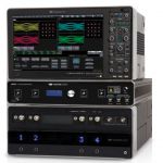 26 September 2016 – Teledyne LeCroy announced two new products for testing optical links. The OE6250G O/E converter is a high performance optical-to-electrical converter available for real-time oscilloscopes, with 25 GHz of optical bandwidth. The IQS25 Coherent Optical Receiver joins the IQS product family as a lower-cost alternative to the high-performance IQS42 and IQS70 receivers, providing a high-value instrument for testing coherent links up to 32 Gbaud.
Teledyne LeCroy previewed HV Fiber-Optically Isolated Probe
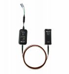 21 September 2016 – Teledyne LeCroy previewed the new HVFO high voltage fiber-optically isolated oscilloscope probe at the IEEE Energy Conversion Congress and Expo (ECCE) 2016 exhibition in Milwaukee, Wisconsin (USA). The HVFO is an affordable, optimally designed probe for measurement of small signals floating on a HV bus in power electronics designs. Optical isolation between the probe tip and the oscilloscope input reduces adverse loading of the device under test (DUT); and also reduces noise, distortion, ringing, overshoots, and transients on the measured signal.
- Evaluation of multi-channel coherent Modulation Schemes
- Teledyne LeCroy launches new 10-Bit High Definition Oscilloscopes
- Tektronix starts Delivery of Optically Isolated Probe System
- Debugging of MIPI M-PHY Interfaces
- Tektronix enhances Portfolio with new basic Oscilloscope
- SIGLENT expands SDS1000X Series Digital Oscilloscope Series
- New Release of BenchVue Software enables Data Logging with Oscilloscopes
Page 49 of 78
Oscilloscope Basics |
Oscilloscope Probes – Vital Link in the Measurement Chain
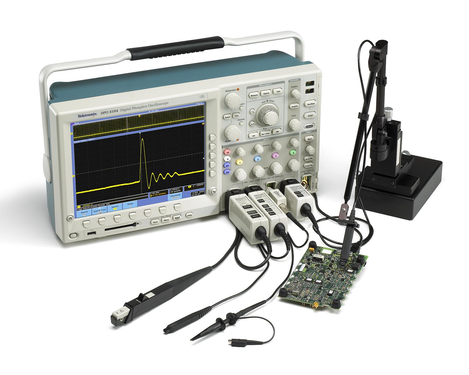 Signal measurement results can only be as accurate as the test and measurement tools in use. As clock rates and edge speeds of today’s electronic circuits increase, probing becomes a critical piece of the measurement system – the component that comes in direct contact with your circuit. This article looks at voltage probing considerations for embedded system and digital design debugging applications.
Oscilloscope Background |
A simple method to verify the bandwidth of your probe
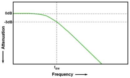 In oscilloscopes or oscilloscope probes, bandwidth is a measure of the width of a range of frequencies measured in Hertz. Specifically, bandwidth is specified as the frequency at which a sinusoidal input signal is attenuated to 70.7 percent of its original amplitude, also known as the -3 dB point. Most oscilloscope companies design the scope/probe response to be as flat as possible throughout its specified frequency range, and most customers simply rely on the specified bandwidth of the oscilloscope or oscilloscope probes, wondering if they are indeed getting the bandwidth performance at the probe tip. Now you can use these step-by-step instructions to simply measure and verify the bandwidth of your probe with an oscilloscope you may already have.