Did you know? |
Can a digitizer be used as an oscilloscope? Read more...
Latest Oscilloscope News |
PicoScope breaks the 100,000 waveforms per second barrier!
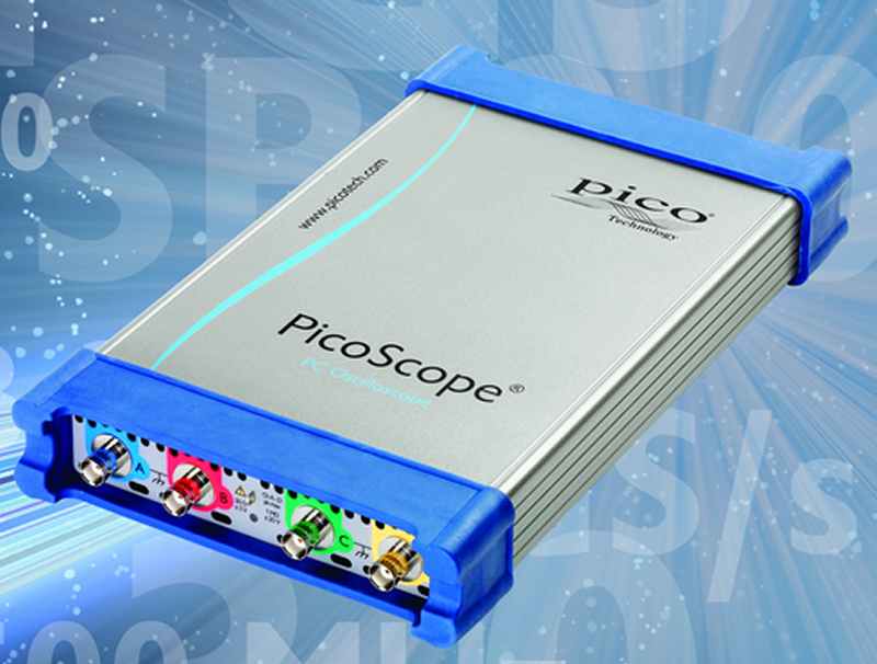 02 December 2014 - Pico Technology improved its PicoScope 6 software for PC oscilloscopes and increased the continuous update rate to more than 100,000 waveforms per second. This is faster than any other PC oscilloscope, and beats many expensive benchtop oscilloscopes too.
Test, Debug and Analysis Tools for the entire DDR Design Cycle
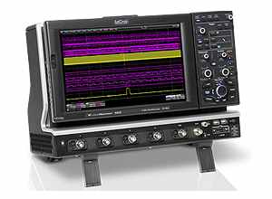 01 December 2014 — Teledyne LeCroy introduces the DDR Debug Toolkit for complete physical layer analysis of DDR 2/3/4 and LPDDR2/3 signals. Most oscilloscope-based DDR physical layer test tools on the market are targeted exclusively at JEDEC compliance testing, whereas the DDR Debug Toolkit provides test, debug and analysis tools for the entire DDR design cycle, making it the ultimate DDR analysis package. The DDR Debug Toolkit includes numerous, time saving industry firsts to simplify DDR testing.
Rigol releases Software for Testing Switching Power Supplies
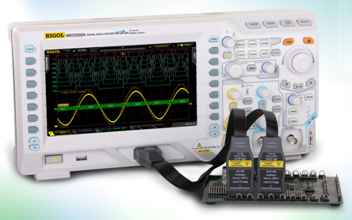 28 November 2014 – Rigol Technologies EU has released a new PC Software, which enables users to perform standard measurements on switching power supplies. This software, in combination with Rigol oscilloscopes (series DS/MSO2000A, DS4000 or DS6000) allows customers to set up small test systems, which represent a reasonably priced alternative for measuring switching power supply parameters during the development phase.
New Measurement and Graphing Capabilities for CAN FD Analysis
27 November 2014 – Teledyne LeCroy announced the addition of unique measurement and graphing capabilities to their CAN Flexible Data-Rate (FD) serial trigger and decode solution. The new CAN FD solution (CAN FD TDM) enables designers using this new standard to gain unprecedented insight in to their systems, correlating physical layer signals and protocol layer data on a single display while also measuring and plotting bus performance. These tools can be used to measure the time between two CAN or CAN FD messages, or from a message to an analog signal. These measurements can then be extracted to recreate analog waveforms.
Transmitter Testing Solution for USB 3.1
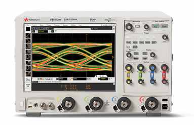 26 November 2014 – Keysight Technologies introduced transmitter (TX) test support for the USB 3.1 specification with the U7243B USB 3.1 transmitter performance validation and compliance test software. The test software allows authorized test centers to certify SuperSpeed USB and SuperSpeed USB 10-Gbps devices and gives in-house test and performance validation engineers the tools to ensure their devices comply with the USB 3.1 specification. The test software operates on Keysight’s 90000 X-, Q- and Z-Series Infiniium real-time oscilloscopes with bandwidths of 16 GHz and higher. Access to the test signals through a USB test fixture is required.
Reconfigurable 8 Channel Oscilloscope with 14-bit Resolution
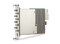 25 November 2014 - National Instruments introduced with the NI PXIe-5171R a reconfigurable oscilloscope with eight calibrated analog input channels, 250 MHz bandwidth, 250 MS/s sample rate, and 14-bit resolution. The PXIe-5171R is a general-purpose module that features a user-programmable FPGA for inline signal processing, protocol decoding, and advanced trigger schemes without dead time.
Rigol introduces new 50MHz Economy Digital Oscilloscope
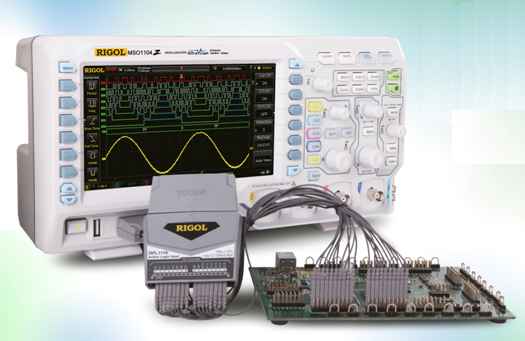 24 November 2014 – Rigol Technologies EU announced the expansion of their DS1000Z Mid-Range Digital Oscilloscope series with a 50 MHz version with a large 7” screen. The DS1054Z version incorporates most of Rigol’s breakthrough technologies and delivers superior performance and functions. The new model was mainly designed for first-time-users and also for education, technical schools and universities as well as teaching labs, test and physics labs.
- 10 Tips for selecting an Oscilloscope
- High Bandwidth, low Noise Oscilloscope Probe for Power Integrity Measurements
- Verification of MIPI D-PHY Interfaces
- USB Oscilloscope Drivers for BeagleBone Black and Raspberry Pi
- Passive Oscilloscope Probes operate over wide Temperature Range
- Tektronix releases Test Solution for MIPI M-PHY Specification v3.1
- CAN FD and SENT Triggering and Decode Options
Page 69 of 78
Oscilloscope Basics |
Oscilloscope Probes – Vital Link in the Measurement Chain
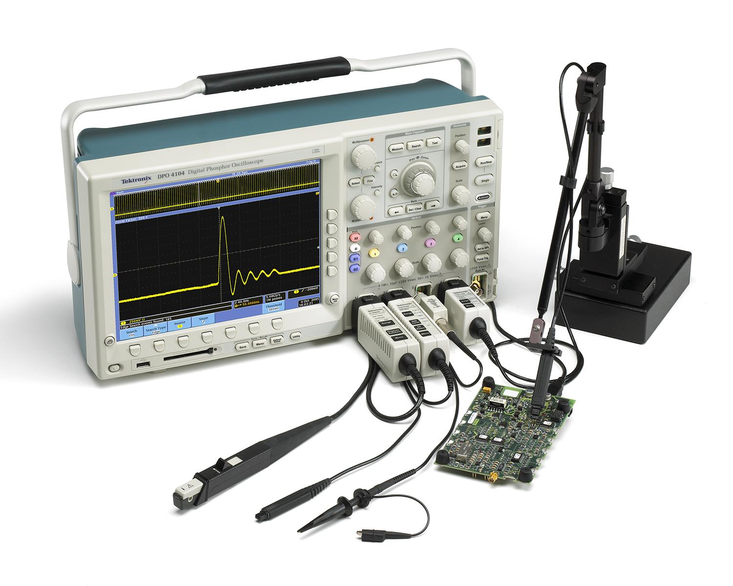 Signal measurement results can only be as accurate as the test and measurement tools in use. As clock rates and edge speeds of today’s electronic circuits increase, probing becomes a critical piece of the measurement system – the component that comes in direct contact with your circuit. This article looks at voltage probing considerations for embedded system and digital design debugging applications.
Oscilloscope Background |
A simple method to verify the bandwidth of your probe
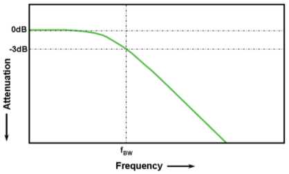 In oscilloscopes or oscilloscope probes, bandwidth is a measure of the width of a range of frequencies measured in Hertz. Specifically, bandwidth is specified as the frequency at which a sinusoidal input signal is attenuated to 70.7 percent of its original amplitude, also known as the -3 dB point. Most oscilloscope companies design the scope/probe response to be as flat as possible throughout its specified frequency range, and most customers simply rely on the specified bandwidth of the oscilloscope or oscilloscope probes, wondering if they are indeed getting the bandwidth performance at the probe tip. Now you can use these step-by-step instructions to simply measure and verify the bandwidth of your probe with an oscilloscope you may already have.